normal mode
• Switch on ignition.
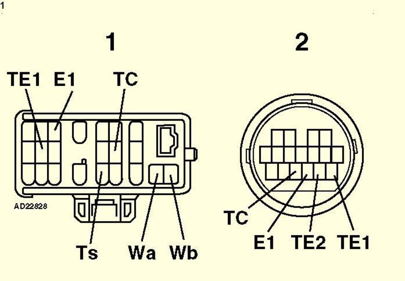
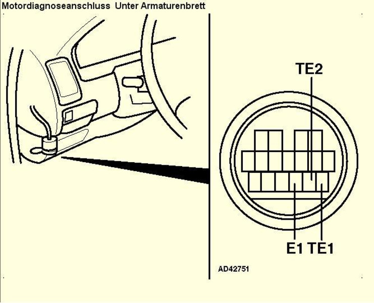
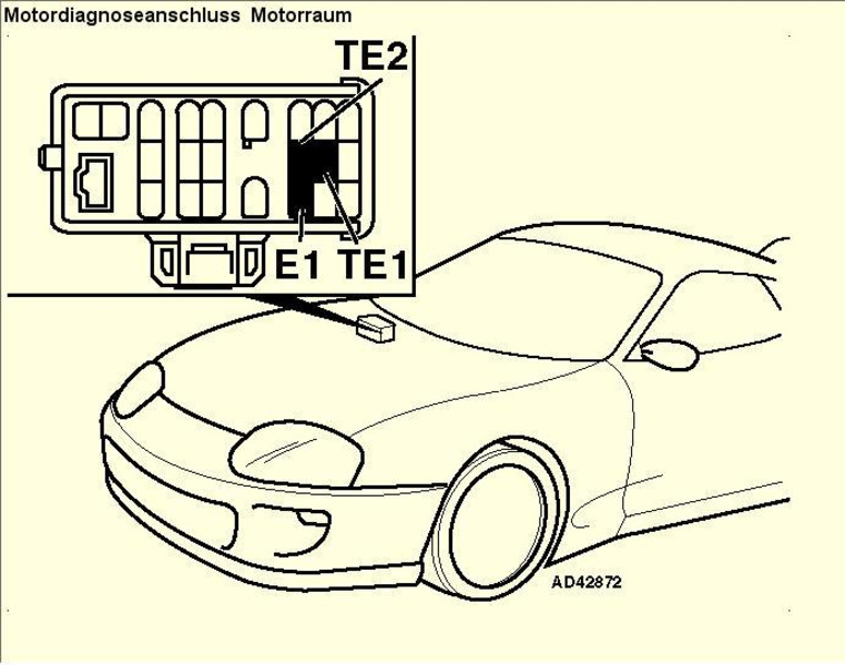
• Bridge the outputs Et and TE1 of the diagnostic connection (Fig. 1) [1] or (Fig. 1) [2].
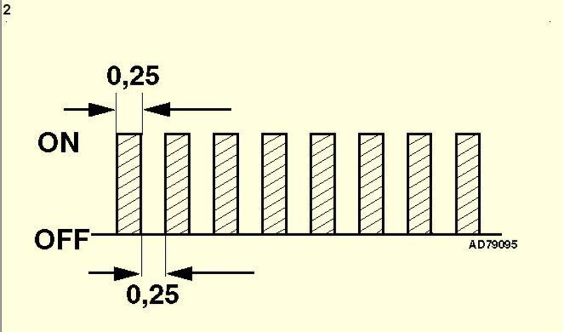
• If no fault codes are set, the light flashes twice per second Fig. 7.
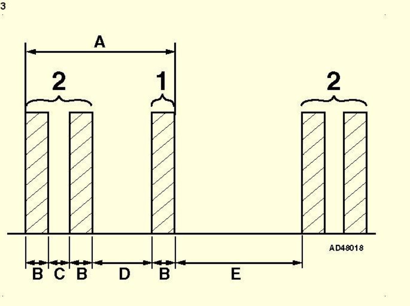
• Each error code consists of two groups of one or more flashing signals each (Fig. 3) [A].
• Flash duration 0.5 seconds (Fig. 3) [B].
• The individual flashing signals are separated by pauses of 0.5 seconds (Fig. 3) [C].
• The individual error code groups are separated by pauses of 1.5 seconds (Fig. 3) [D].
• The individual error codes are separated by pauses of 2.5 seconds (Fig. 3) [E]
• Example: Two flashes with a duration of 0.5 seconds - Pause of 1.5 seconds - A flash signal with a duration of 0.5 seconds. Error code 21 (fig. 3) - heated lambda probe 1.
• The last error code is followed by a pause of 4.5 seconds. Thereafter, the stored error codes are repeated.
• Count the engine failure warning lamp flashing signals. Note the error codes. Compare with error code table.
• Disconnect the jumper cable.
• Switch off the ignition. • Correct the errors displayed.
test mode
• Switch off the ignition.
• Bridge the outputs El and TE2 of the diagnostic connection (Fig. 1) [2].
• Switch on ignition.
• Engine trouble warning lamp must flash four times per second.
• Start the motor.
• Drive the vehicle to establish the operating conditions under which the malfunction occurs, according to the customer.
• Stop the vehicle. Do not switch off the ignition.
• For short-circuited outputs El and TE2 of the diagnostic connection, bridge outputs El and TE1 (Fig. 1).
• Count the flashing signals of the engine trouble warning light. Note the error codes. Compare with error code table.
• Switch off the ignition.
• Disconnect both jumper cables.
• Correct the errors displayed.
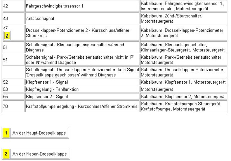
NOTE: Failure to do so may result in error code 43 being set. If done correctly, error code 51 will be generated automatically, which can be ignored.
deletion
NOTE: If the ambient temperature is low, the fuse must be removed for a longer period.
• Switch off the ignition.
• Remove the fuse EFI no. 1 (30 A) from the fuse box in the engine compartment for at least 10 seconds Fig. 4.
• Reinstall the fuse.
• Erasing the DTC entries can also be done by disconnecting the battery cables.
ATTENTION: Disconnecting the battery can erase the memory contents of electronic components (eg radio and clock).
• Repeat the test procedure to ensure that all entries in the fault memory of the engine control unit are deleted.
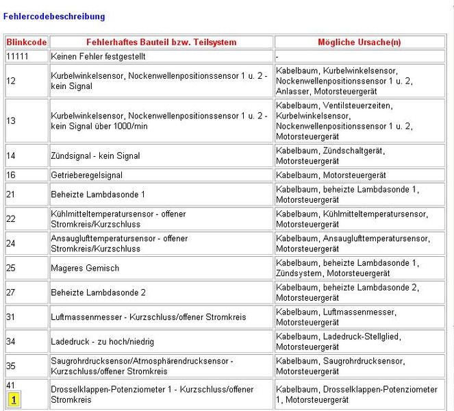
error codes
